Yamaha YSP-600 Service Manual
Digital sound projector
Hide thumbs
Also See for YSP-600:
- Owner's manual (556 pages) ,
- Service manual (99 pages) ,
- Owner's manual (98 pages)
Advertisement
Table of Contents
- 1 Table of Contents
- 2 Service Manual
- 3 To Service Personnel
- 4 Rear Panels
- 5 Front Panels
- 6 Ysp-600/Hty
- 7 Specifications
- 8 Updating Firmware
- 9 Self-Diagnostic Function
- 10 Display Data
- 11 Pin Connection Diagrams
- 12 Block Diagrams
- 13 Printed Circuit Boards
- 14 Schematic Diagrams
- 15 Replacement Parts List
- 16 Remote Control
- Download this manual
See also:
Owner's Manual
YSP-600/HTY-760
This manual has been provided for the use of authorized YAMAHA Retailers and their service personnel.
It has been assumed that basic service procedures inherent to the industry, and more specifically YAMAHA Products, are already
known and understood by the users, and have therefore not been restated.
WARNING:
IMPORTANT:
The data provided is believed to be accurate and applicable to the unit(s) indicated on the cover. The research, engineering, and
service departments of YAMAHA are continually striving to improve YAMAHA products. Modifications are, therefore, inevitable
and specifications are subject to change without notice or obligation to retrofit. Should any discrepancy appear to exist, please
contact the distributor's Service Division.
WARNING:
IMPORTANT:
I CONTENTS
TO SERVICE PERSONNEL .......................................... 2
FRONT PANELS ............................................................ 3
REAR PANELS .......................................................... 4-5
REMOTE CONTROL PANELS ...................................... 6
参考仕様
INTERNAL VIEW ........................................................... 9
SERVICE PRECAUTIONS /
DISASSEMBLY PROCEDURES /
ファームウェアの書き込み
......................................... 24-31
......................................... 32-52
ダイアグ(自己診断機能)
1 0 1 0 9 3
DIGITAL SOUND PROJECTOR
Failure to follow appropriate service and safety procedures when servicing this product may result in personal
injury, destruction of expensive components, and failure of the product to perform as specified. For these reasons,
we advise all YAMAHA product owners that any service required should be performed by an authorized
YAMAHA Retailer or the appointed service representative.
The presentation or sale of this manual to any individual or firm does not constitute authorization, certification or
recognition of any applicable technical capabilities, or establish a principle-agent relationship of any form.
Static discharges can destroy expensive components. Discharge any static electricity your body may have
accumulated by grounding yourself to the ground buss in the unit (heavy gauge black wires connect to this buss).
Turn the unit OFF during disassembly and part replacement. Recheck all work before you apply power to the unit.
...................................... 7-8
サービス時の注意事項
......... 9
分解手順
........... 10-23
2008
This manual is copyrighted by YAMAHA and may not be copied or
redistributed either in print or electronically without permission.
SERVICE MANUAL
IMPORTANT NOTICE
IC DATA ................................................................. 54-62
PIN CONNECTION DIAGRAMS .................................. 63
BLOCK DIAGRAMS .............................................. 64-65
PRINTED CIRCUIT BOARDS................................ 66-74
SCHEMATIC DIAGRAMS ...................................... 75-79
REPLACEMENT PARTS LIST .............................. 81-95
REMOTE CONTROL .............................................. 96-97
ADJUSTING SYSTEM PARAMETERS /
................................................................... 98
拡張メニュー
All rights reserved.
P.O.Box 1, Hamamatsu, Japan
'08.04
Advertisement
Table of Contents

Related Manuals for Yamaha YSP-600


Summary of Contents for Yamaha YSP-600
-
Page 1: Table Of Contents
This manual has been provided for the use of authorized YAMAHA Retailers and their service personnel. It has been assumed that basic service procedures inherent to the industry, and more specifically YAMAHA Products, are already known and understood by the users, and have therefore not been restated. -
Page 2: To Service Personnel
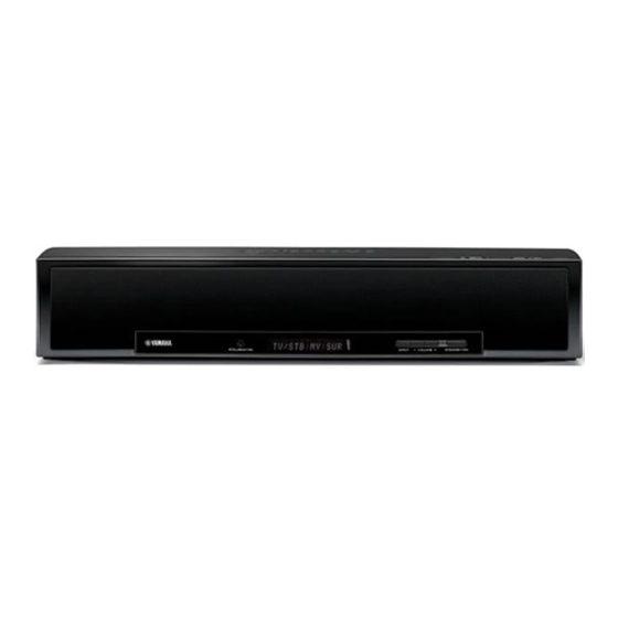
YSP-600/HTY-760 I TO SERVICE PERSONNEL AC LEAKAGE WALL EQUIPMENT TESTER OR 1. Critical Components Information OUTLET UNDER TEST EQUIVALENT Components having special characteristics are marked s and must be replaced with parts having specifications equal to those originally installed. 2. Leakage Current Measurement (For 120V Models Only) - Page 3 YSP-600/HTY-760 I FRONT PANELS YSP-600 (U, C, T, K, A, B, G, E, F, L, V, J models) HTY-760 (B, G, E, F models) YSP-600 (U, C, T, K, A, B, G, E, F, L, V models) YSP-600 (J model)
-
Page 4: Rear Panels
YSP-600/HTY-760 I REAR PANELS YSP-600 (U, C models) YSP-600 (T, K, A, B, G, E, F, L, V models) HTY-760 (B, G, E, F models) YSP-600 (J model) YSP-600 (U, C models) (T model) (K model) - Page 5 YSP-600/HTY-760 (A model) (B model) (G, E, F models) (L model) (V model) (J model) HTY-760 (B model) (G, E, F models)
- Page 6 YSP-600/HTY-760 I REMOTE CONTROL PANELS YSP-600 YSP-600 YSP-600 (U model) (C, T, K, A, B, G, E, F, L, V models) (J model) HTY-760 (B, G, E, F models) STANDBY/ON POWER POWER STANDBY/ON POWER POWER INPUT1 INPUT2 MACRO INPUT1 INPUT2...
- Page 7 Type / 型式 ..........2-way acoustic suspension Labs,Inc.からのライセンスに基づき製品化されています。 Audio Format / 音声フォーマット Magnetic shielding type The “ ” logo and “IntelliBeam” are trademarks of YAMAHA Cor- ........PCM, Dolby Digital, DTS, AAC (J model) poration. Driver / スピーカーユニット 「インテリビーム」 「 IntelliBeam」 は、ヤマハ株式会社の商標です。...
- Page 8 YSP-600/HTY-760...
- Page 9 YSP-600/HTY-760 I INTERNAL VIEW Front view Rear view DRIVER WOOFER DRIVER TWEETER INPUT (5) P.C.B. INPUT (3) P.C.B. INPUT (4) P.C.B. DSP P.C.B. 7 HDMI P.C.B. INPUT (2) P.C.B. INPUT (1) P.C.B. I SERVICE PRECAUTIONS / サービス時の注意事項 Safety measures 安全対策...
- Page 10 YSP-600/HTY-760 I DISASSEMBLY PROCEDURES / 分解手順 (Remove parts in the order as numbered.) (番号順に部品を取り外してください。) 分解・組立時の注意: Cautions for disassembly and reassembly: • Disconnect the power cable from the AC outlet. ・ AC電源コンセントから、電源コードを抜いてください。 ・ やわらかい布等を敷いて その上で作業を行ってくだ • Spread soft cloth or the like and perform the work on it.
- Page 11 YSP-600/HTY-760 2. トップカバーの外し方 2. Removal of Top Cover a. 7 のネジ6本、 8 のネジ4本、 9 のネジ9本を外しま a. Remove 6 screws (7), 4 screws (8) and 9 screws す。 (Fig. 2) (9). (Fig. 2) b. Remove the top cover rearward. b. トップカバーを後方に取り外します。...
-
Page 12: Front Panels
YSP-600/HTY-760 3. グリルフロントの外し方 3. Removal of Grille Front a. 0 のネジ5本、 A のネジ4本を外します。 (Fig. 3) a. Remove 5 screws (0) and 4 screws (A). (Fig. 3) b. フロントパネルを前方にゆっくり取り外します。 (Fig. 3) b. Remove the front panel forward gradually. (Fig. 3) c. B のネジ12本、 C のネジ2本を取り外します。 (Fig. 3)... - Page 13 YSP-600/HTY-760 5. HDMI P.C.B.の外し方 5. Removal of HDMI P.C.B. a. E のネジ12本を外します。 (Fig. 4) a. Remove 12 screws (E). (Fig. 4) b. F のネジ3本を外します。 (Fig. 4) b. Remove 3 screws (F). (Fig. 4) c. Remove the frame top. (Fig. 4) c.
- Page 14 YSP-600/HTY-760 6. DSP P.C.B.の外し方 6. Removal of DSP P.C.B. a. I のネジ6本を外します。 (Fig. 5) a. Remove 6 screws (I). (Fig. 5) b. CB203-207、CB601-607を外します。 (Fig. 5) b. Remove CB203-207 and CB601-607. (Fig. 5) c. Remove the DSP P.C.B.. (Fig. 5) c. DSP P.C.B.を取り外します。 (Fig. 5)...
- Page 15 YSP-600/HTY-760 f. CB901を外します。 (Fig. 7) f. Remove CB901. (Fig. 7) g. N のネジ5本を外します。 (Fig. 7) g. Remove 5 screws (N). (Fig. 7) h. Remove CB4, CB7 and CB8. (Fig. 7) h. CB4、CB7-8を外します。 (Fig. 7) INPUT (1) P.C.B.を取り外します。 (Fig. 7) Remove the INPUT (1) P.C.B.. (Fig. 7) Remove CB801.
-
Page 16: Ysp-600/Hty
YSP-600/HTY-760 When checking the P.C.B.s: P.C.B.をチェックする場合には: ・ 本機の上にゴムシートと布を敷き、その上にP.C.B.を * Put the rubber sheet and cloth over this unit. Then place the P.C.B.s upside down on the cloth and check 裏返しに置いてチェックします。 (Fig. 8) ・ 外したケーブル (コネクター) をすべて接続します。 it. (Fig. 8) ・ カード電線を接続する際、極性に注意してください。... - Page 17 YSP-600/HTY-760 スピーカーユニットまでの分解手順 Disassembly Procedures as far as Driver Woofer/Tweeter 1. ボトムカバーの外し方 1. Removal of Bottom Cover a. 1 のネジ3本を外し、パネルサイドLを取り外します。 a. Remove 3 screws (1) and then remove the side panel (Fig. 9) L. (Fig. 9) b. 2 のネジ3本を外し、パネルサイドRを取り外します。 b. Remove 3 screws (2) and then remove the side panel (Fig.
- Page 18 YSP-600/HTY-760 2. トップカバーの外し方 2. Removal of Top Cover a. 7 のネジ6本、 8 のネジ4本、 9 のネジ9本を外しま a. Remove 6 screws (7), 4 screws (8) and 9 screws す。 (Fig. 10) (9). (Fig. 10) b. Remove the top cover rearward. b. トップカバーを後方に取り外します。...
- Page 19 YSP-600/HTY-760 3. グリルフロントの外し方 3. Removal of Grille Front a. 0 のネジ5本、 A のネジ4本を外します。 (Fig. 11) a. Remove 5 screws (0) and 4 screws (A). (Fig. 11) b. フロントパネルを前方にゆっくり取り外します。 (Fig. 11) b. Remove the front panel forward gradually. (Fig. 11) c. B のネジ12本、 C のネジ2本を取り外します。...
- Page 20 YSP-600/HTY-760 5. フレームフロントの外し方 5. Removal of Frame Front a. E のネジ4本、 F のネジ1本を外します。 (Fig. 12) a. Remove 4 screws (E) and screw (F). (Fig. 12) b. CB801、CB903を外します。 (Fig. 12) b. Remove CB801 and CB903. (Fig. 12) c. Remove the frame front together with P.C.B.s. (Fig. 12) c.
- Page 21 YSP-600/HTY-760 6. フレームメインの外し方 6. Removal of Frame Main a. G のネジ12本、 H のネジ3本を外します。 (Fig. 13) a. Remove 12 screws (G) and 3 screws (H). (Fig. 13) b. フレームトップを取り外します。 (Fig. 13) b. Remove the frame top. (Fig. 13) c. I のネジ6本、 J のネジ4本、 K のネジ2本を外しま...
- Page 22 YSP-600/HTY-760 8. スピーカーユニット (ツィーター) の外し方 8. Removal of Driver Tweeter a. P のネジ4本を外し、INPUT (3) P.C.B.を取り外しま a. Remove 4 screws (P) and then remove the INPUT (3) す。 (Fig. 14) P.C.B.. (Fig. 14) b. Q のネジ12本を外します。 (Fig. 14) b. Remove 12 screws (Q). (Fig. 14) c.
- Page 23 YSP-600/HTY-760 スピーカーユニット (ツイーター) の取り付け方 Installation of Driver Tweeter Note: Make sure that all the removed driver tweeter 注意: 取り外したスピーカーユニット (ツイーター) はす べて決められた位置に取り付けてください。 parts are reinstalled at specified positions. (Fig. 15) (Fig. 15) Pin No. (cable color) / ピンNo. CB601 CB602...
-
Page 24: Specifications
YSP-600/HTY-760 I UPDATING FIRMWARE / ファームウェアの書き込み After replacing the following parts with the replacement 下記の部品をサービス部品に交換した場合、下記の手順 により最新のファームウェアの書き込みを行ってくださ parts, update the latest firmware according to the following procedure. い。 DSP P.C.B. DSP P.C.B. DSP P.C.B.のマイコン (IC211) Microprocessor (IC211) of DSP P.C.B. DSP P.C.B.のDSP (TI Flash ROM、IC212)... - Page 25 YSP-600/HTY-760 G Operation Procedure ● 操作方法 Writing to the microprocessor マイコンへの書き込み 1. 本機の電源を切り、電源コードをACコンセントから抜 1. Turn off the power of this unit and disconnect the power cable from the AC outlet. きます。 2. Connect the writing port of this unit to the serial port 2.
- Page 26 YSP-600/HTY-760 6.[Refer...] をクリックし、書き込むファームウェアを選 6. Click [Refer...], and select the firmware name. (Fig. 3) * The ID code and MCU type are 択します。 (Fig. 3) ※ ID、およびMCU Typeは書き込みファイル loaded when the file is se- 選択時、自動的に取り込まれます。 (Fig. 3) lected. (Fig. 3) Click [OK]. (Fig. 3) [OK]...
-
Page 27: Self-Diagnostic Function
YSP-600/HTY-760 9. プログラムの送信が終了すると、下記の画面が表示され 9. When the program transmission is completed, the screen appears as shown below. ます。 [OK] をクリックします。 (Fig. 6) Click [OK]. (Fig. 6) 10. Click [EXIT], to end “FlashSta.exe”. (Fig. 6) 10. [EXIT] をクリックして、 “FlashSta.exe” を終了します。 (Fig. 6)... - Page 28 YSP-600/HTY-760 4. ダイアグ “19-2. checksum” を選択します。 4. Select the self-diagnostic function menu “19-2. checksum”. 表示されたチェックサムが書き込んだファームウェアの Check that the displayed checksum is the same as the チェックサムと同じであることを確認します。 written firmware checksum. CHECK SUM:148D ※ 表 示 さ れ た フ ァ ー ム ウ ェ ア の バ ー ジ ョ ン お よ び...
- Page 29 YSP-600/HTY-760 3. 送信データ、ポートを選択します。 3. Select the data and port. ・ DSP HEX FILE · DSP HEX FILE Select “YSP600_data1_Verx_xr.hex”. “YSP600_data1_Verx_xr.hex” を選択します。 · RS232C ・ RS232C 接続しているRS-232Cポートを選択します。 Select the port of RS-232C. When [Refer...] is clicked, the open file screen is displayed.
- Page 30 YSP-600/HTY-760 5. 本機の電源コードをACコンセントに接続し、本機の 5. Connect the power cable of this unit to the AC outlet. While pressing the “VOL+” key and “VOL-” key of this “VOL+” キーと “VOL-” キーを押しながら、リモコンの “電 源” キーを押し、ダイアグを起動します。 unit, press the “STANDBY/ON” key of the remote con- trol to activate the self-diagnostic function.
- Page 31 YSP-600/HTY-760 7. SUM値を確認します。 7. Check the SUM. After downloading successfully, the value of “SUM from 書き込み完了後 “SUM from SET” が表示されます。 “SUM from FILE” と “SUM from SET” の値が同じになれ SET” is appeared. The procedure is completed when the value of “SUM ば完了です。...
- Page 32 YSP-600/HTY-760 I SELF-DIAGNOSTIC FUNCTION / ダイアグ (自己診断機能) This unit has self-diagnostic functions that are intended for 本機には、検査、測定、不良個所の発見を目的にしたダイ Main menu Sub-menu inspection, measurement and location of faulty point. アグ (自己診断機能) があります。 DOCK CHECK ( Not applied to these 1. LOOP TEST/ACC PWR/CONNECT There are 21 main menu items, each of which has sub- メインメニューは21個あり、そのそれぞれにサブメニュー...
- Page 33 YSP-600/HTY-760 • Starting Self-Diagnostic Function ● ダイアグの起動 To activate the self-diagnostic function, press the 本機の下図に示すキーを同時に押しながらリモコンの “電 “STANDBY/ON” key of the remote control while pressing 2 源” キーを押すと、ダイアグが起動します。 keys of this unit as shown below at the same time. Panel key of this unit / 本機のパネルキー...
- Page 34 YSP-600/HTY-760 • Display provided when Self-Diagnos- ● ダイアグ起動時の表示 tic Function started モニターを接続してある場合は、モニターの画面に下図の ようにメインメニューの一覧が表示されます。 (ダイアグ When the monitor is connected, the list of main menu を解除するまで、この表示が保持されます) items is displayed on the monitor screen as shown below. (This list remains on display until the self diagnostic function is cancelled.)
- Page 35 YSP-600/HTY-760 Version (1 alphabet) バージョン (英1文字) D-I_PROTECT C 原因: アンプICが異常。 Cause: Amplifier IC is abnormal. 異常状態のまま電源オンすると、2秒後にプロテクション Turning on the power without correcting the cause will trigger the protection function to work 2 second later to がかかり、電源が切れます。 shut off the power supply.
- Page 36 YSP-600/HTY-760 • Display during Self-Diagnostic Func- ● ダイアグ動作中の表示 tion operation ダイアグ動作中、モニター画面には起動画面の項で説明し たメニュー一覧が表示されます。本機のFLディスプレイに During the self-diagnostic function operation, the menu list は動作中の機能が表示されます。機能動作中の表示内容に described in the section of the startup screen appears on ついては、後述の機能詳細で記述します。 the TV screen and the function at work is indicated on the FL display.
- Page 37 YSP-600/HTY-760 • Details of Self-Diagnostic Function menu ● ダイアグメニュー詳細 1. DSP THROUGH 1. DSP THROUGH The signal is not changed into beam and output from ビーム化は行わず、サブメニューの指定CHから出力し the channel specified by the sub-menu. ます。 When 2CH signals are input, they are distributed as 2CH信号入力時はDSP (IC206 DSP P.C.B.)...
- Page 38 YSP-600/HTY-760 [Digital] YDA141-SZ Tweeter Digital input YDA141-SZ Tweeter D-AMP Analog input Woofer L/R (SUBWOOFER OUT) [Analog] YDA141-SZ Tweeter Digital input YDA141-SZ Tweeter D-AMP Analog input Woofer L/R (SUBWOOFER OUT)
- Page 39 YSP-600/HTY-760 2. RAM THROUGH 2. RAM THROUGH The signal is not changed into beam and output from ビーム化は行わず、サブメニューの指定CHから出力し the channel specified by the sub-menu. ます。 2CH信号入力時はDSP (IC206 DSP P.C.B.) にて以下の When 2CH signals are input, they are distributed as follows at DSP (IC206 DSP P.C.B.).
- Page 40 YSP-600/HTY-760 3. PRO LOGIC / Neo:6 3. PRO LOGIC / Neo:6 PRO LOGIC I, II, Neo:6 can be selected from the sub- サブメニューでPRO LOGIC I、II、Neo:6を選択可能で menu items. す。 PRO LOGIC I (PRO LOGIC EMULATION) PRO LOGIC I (PRO LOGIC EMULATION)...
- Page 41 OSD OFF / OSD表示オフ OSD characters 1 ON / OSDキャラクター1表示オン All segments ON (dimmer 50 %) / 全セグメント点灯 (ディマー50 %) [Sample: YSP-600 (G model)] OSD characters 2 ON / OSDキャラクター2表示オン Lighting of segments in lattice / セグメント格子状点灯 Lighting in lattice / 格子状点灯...
- Page 42 YSP-600/HTY-760 6. MANUAL TEST 6. MANUAL TEST The noise generator with a built-in DSP outputs the DSP内蔵のノイズ発生回路によって、サブメニューで test noise through the channels specified by the sub- 指定したチャンネルへテストノイズを出力します。 LFE用のノイズ周波数は30∼80Hz、それ以外は500∼2 menu. The noise frequency is 30 to 80Hz for LFE and 500 to kHzとなります。...
- Page 43 YSP-600/HTY-760 7. RS-232C 7. RS-232C This menu is used to check transmission of the data データ送受信チェック、ハードウェアフローポート and the flow port of the hardware. チェックを行うメニューです。 パワーオフ状態にしてから、RS232C端子の2ピン With the power turned off, short between pins No. 2 (RxD) and No. 3 (TxD), and between pins No. 7 (RTS) (RxD)...
- Page 44 YSP-600/HTY-760 9. AD DATA CHECK 9. AD DATA CHECK This menu is used to display the A/D conversion value 本機のパネルキー、プロテクションなどを検出している of the main microprocessor which detects panel keys メインマイコンのA/D変換の値を、サブメニューで%表示 します。信号処理は実行前の状態を維持します。 of this unit and protection functions in % using the sub- menu.
- Page 45 YSP-600/HTY-760 10. IF STATUS 10. IF STATUS (Input function status) Using the sub-menu, the status data is displayed one サブメニュー操作により、以下のステータス情報を順次 after another in the hexadecimal notation. 16進数で表示します。信号処理は、本メニュー実行前の 状態を維持します。 During signal processing, the status before execution of this menu is maintained.
- Page 46 YSP-600/HTY-760 11. DOCK CHECK 11. DOCK CHECK Not applied to these models. このモデルには適用されません。 11.DOCK:NG NNY 12. XM CHECK 13. DAB CHECK Not applied to these models. Not applied to these models. DAB SCL 1 kHz, -1 dB / 44.1 kHz...
- Page 47 The product ID of this unit written in HDMI module is displayed. HDMIモジュールに書き込まれている本機のプロダクトIDを表示します。 3306: YSP-600 3307: HTY-760 HDMI vendor name HVN:YAMAHA The vendor name “YAMAHA” of this unit written in HDMI module is displayed. HDMIモジュールに書き込まれている本機のベンダ名 “YAMAHA” を表示します。 CEC (Consumer Electronics Control) receive data CEC:00-00-00-0 The CEC information is displayed. CEC情報を表示します。...
- Page 48 YSP-600/HTY-760 17. VIDEO CONVERSION 17. VIDEO CONVERSION Not applied to these models. このモデルには適用されません。 I2C CHECK I2C CHECK I2C:0000000 DIGITAL COMPONENT DIGITAL COMPONENT DIGITAL COMP DIGITAL CVBS DIGITAL CVBS DIGITAL CVBS DIGITAL Y/C DIGITAL Y/C DIGITAL Y/C ANALOG BYPASS ANALOG BYPASS...
- Page 49 MODEL NAME YSP-600を表示します。 YSP-600 or HTY-760 is displayed. MODEL:YSP-600 DESTINATION DESTINATION Jを表示します。 UC, TABGEFL (YSP-600), KV or BGEF (HTY-760) is dis- played. DEST : GE VIDEO FORMAT VIDEO FORTMAT NTSC (U, C, K, V models) NTSC PAL (T, A, B, G, E, F, L models) VIDEO: PAL 19.
- Page 50 YSP-600/HTY-760 20. DATE 20. DATE The updated date of the program, clearance of the プログラムの更新日付、プロテクション履歴のクリ protection history and the remote control reception ア、リモコン受信コードを表示します。 Remo Codeのメニューにすると、リモコンの全キーの code are displayed. When Remo Code menu is selected, keys become 値を検出するためキー操作はできなくなりますが、本 機の “I N P U T ” キーを押すことにより、次のサブメ...
- Page 51 YSP-600/HTY-760 21. DSP CHECK 21. DSP CHECK Tx Test Ch Tx Test Ch 各スピーカーユニットを鳴らし、不良・取付位置の確認を Have the sound produced from each driver to check its condition and installation position. します。 リモコンの “決定” 、 “戻る” キーを使って選択します。 Use the “ENTER” and “RETURN” keys of the remote control for selection.
- Page 52 YSP-600/HTY-760 RS232C RS232C Use the “ENTER” and “RETURN” keys of the remote リモコンの “決定” 、 “戻る” キーを使って選択します。 control for selection. RS232C: YAMAHA Cert Mode Cert Mode 試験用の特殊モードを選択します。 Select the special mode for testing. Cert.Mode[OFF] * Be sure to set to “OFF”...
-
Page 53: Display Data
YSP-600/HTY-760 I DISPLAY DATA G V901 : 15-BT-115GNKF (INPUT P.C.B.) PATTERN AREA G PIN CONNECTION Pin No. Connection 24 23 22 21 20 19 Pin No. Connection P32 P33 P34 P35 NX NX Note : 1) F1, F2 ..Filament 2) NP .. - Page 54 YSP-600/HTY-760 I IC DATA IC206: D70YE101BRFP266 (DSP P.C.B.) Decoder/Post processor No replacement part available. / サービス部品供給なし Program/Data JTAG EMU 256K Bytes McASP0 Data 16 Serializes Program/Data ROM Page1 C67x + Microprocessor 256K Bytes Memory Data Controller Program/Data McASP1 ROM Page2...
- Page 55 YSP-600/HTY-760 Function Name Detail of Function TYPE PULL GPIO External memory interface (EMIF) address and control EM_CAS – SDRAM column address strobe EM_WE – SDRAM write enable EM_WE_DQM[0] – Write enable or byte enable for EM_D[7:0] EM_WE_DQM[1] – Write enable or byte enable for EM_D[15:8] EM_CLK –...
- Page 56 YSP-600/HTY-760 Function Name Detail of Function TYPE PULL GPIO AXR0[3] – McASP0 serial data 3 AXR0[4] – McASP0 serial data 4 AXR0[5]/SPI1_SCS – McASP0 serial data 5 or SPI1 slave chip select AXR0[6]/SPI1_ENA – McASP0 serial data 6 or SPI1 enable (Ready) AXR0[7]/SPI1_CLK –...
- Page 57 YSP-600/HTY-760 Function Name Detail of Function TYPE PULL GPIO CVDD Core supply DVDD I/O supply Ground 1) TYPE column refers to pin direction in functional mode. If a pin has more than one function with different directions, the functions are separated with a slash (/).
- Page 58 YSP-600/HTY-760 IC211: M3087BFKBGP (DSP P.C.B.) Microprocessor Port P0 Port P1 Port P2 Port P3 Port P4 Port P5 Port P6 < > < > Peripheral Functions A/D Converter: Clock Generation Circuit 1 circuit Timer (16 bits) Standard: 10 inputs COUT...
- Page 59 YSP-600/HTY-760 Function Port Interrupt Timer UART Analog Intelligent Detail of function name name terminal terminal terminal terminal I/O terminal TxD4/ HDMI-RX/TX. VIDEO-DEC/ENC: I2C (400 kHz) SDA4/ ANEX1 data I/O SRxD4 TB4IN INT8 TB3IN TMR-IN HDMI: 1080p frequency detection (24Hz, 60Hz)
- Page 60 YSP-600/HTY-760 Function Port Interrupt Timer UART Analog Intelligent Detail of function name name terminal terminal terminal terminal I/O terminal INPC11/ TA2OUT/ DIR CS OUTC11/ W/RTP20 ISCLK1 CTS2/ INPC10/ TA1IN/V RTS2/ DIR RESET OUTC10/ ISTxD1 TA1OUT/ TB5IN/ (Pull-up required TA0IN/ SCL2...
- Page 61 YSP-600/HTY-760 Function Port Interrupt Timer UART Analog Intelligent Detail of function name name terminal terminal terminal terminal I/O terminal P131 P131 TI-1 Busy OUTC25 P130 P130 TI-1 Mute OUTC24 TI-1 RDY TI-1 RESET * Connect to Vcc via resistor *Pull-down required...
- Page 62 YSP-600/HTY-760 Function Port Interrupt Timer UART Analog Intelligent Detail of function name name terminal terminal terminal terminal I/O terminal (Pull-up required) INPC13/ P113 P113 CS OUT to E2PROM [L: DATA OUTC13 transmission] P112 P112 P111 P111 P110 P110 AN03 Analog input selection (IN_SEL_1: TC4052BF)
-
Page 63: Pin Connection Diagrams
YSP-600/HTY-760 I PIN CONNECTION DIAGRAMS • ICs TC4013BP TC4052BF TC74HCT08AF TC7SH08FU W9816G6CH-7 WM8738 AN77L04 BR25L320F-W EEPROM D70YE101BRFP266 FA5511N-D1-TE1 TC74HCU04AFEL M3087BFKBGP • Diodes 1: IN 2: OUT 1N4002S AK09 1SS355 MA8100-H 10.3V 3: GND 1SS380 MTZJ27D MA8100-M 10.0V D1NL20U-5083 MA8036 3.6V MA8110-M 11.0V... -
Page 64: Block Diagrams
YSP-600/HTY-760 I BLOCK DIAGRAMS (Writing port for factory) From/To Microprocessor (IC211) (CB201) AUDIO/VIDEO SECTION BLOCK DIAGRAM +12VP(D+12) +3.3V • See page 75, 76 → /ICTIA XTAL (24.576MHz) SCHEMATIC DIAGRAM IC204 PROTN 44-46 OUTPL (XL201) OUTML 39-41 MUTEN 24MD D Amp. - Page 65 YSP-600/HTY-760 POWER SUPPLY SECTION BLOCK DIAGRAM D522 T502 D510 TH501 MGND SWITCHING D528 POWER SUPPLY IC510 +12V D523 Q505 IC504, 505, 511 D+12 IC12 AGND L501 L502 RY501 -24V Q506 D524 AC IN T501 POW_RY F501 D501 S3.3 D507 D503 IC506 S3.3BK...
-
Page 66: Printed Circuit Boards
YSP-600/HTY-760 I PRINTED CIRCUIT BOARDS • Semiconductor Location Ref no. Location Ref no. Location Ref no. Location Ref no. Location D201 D210 IC206 IC213 POINT B-3 XL202 (Pin 20 of IC211) POINT B-2 XL201 (Pin 28 of IC203) POINT B-1 XL601 (Pin 48 of IC601) - Page 67 YSP-600/HTY-760 • Semiconductor Location Ref no. Location Ref no. Location Ref no. Location Ref no. Location D212 D603 D608 Q604 D213 D604 D609 D214 D605 Q601 D601 D606 Q602 D602 D607 Q603 DSP P.C.B. (Side B)
- Page 68 YSP-600/HTY-760 注意) Notes) Safety measures 安全対策 • Some internal parts in this product contain high voltages and are dangerous. Be sure to take safety measures during servicing, such ・ この製品の内部には高電圧部分があり危険です。修理の際は、絶縁性の手袋を使用するなどの安全対策を行ってください。 as wearing insulating gloves. ・ 下記箇所には電源をOFFにした後も電荷が残り、高電圧が維持されており危険です。修理作業前に放電用抵抗 (5 kΩ/10 W) •...
- Page 69 YSP-600/HTY-760 POINT A-2 1 / D521, 2 / Q504 • Semiconductor Location Ref no. Location Ref no. Location Ref no. Location Ref no. Location D502 D512 D520 D533 D504 D513 D521 D536 D521 (C) D507 D514 D527 IC505 D508 D517...
- Page 70 YSP-600/HTY-760 注意) Note) Caution for P.C.B. replacement P.C.B.交換時の注意 When replacing INPUT (1) and INPUT (2) P.C.B.s, be sure to replace them at the same time. Installing either P.C.B. of different version INPUT (1) およびINPUT (2) P.C.B.を交換する場合、必ず同時に行ってください。どちらか片方にバージョンの異なるP.C.B.を from the other may cause failure of operation.
- Page 71 YSP-600/HTY-760 INPUT (2) P.C.B. (Side B) • Semiconductor Location Ref no. Location Ref no. Location POINT A-1 XL1 (Pin 6 of IC8) 12 13 T, K, A, B, G, E, F, L models U, C, T, K, A, B, G, E, F, L, V models...
- Page 72 YSP-600/HTY-760 INPUT (3) P.C.B. (Side A) CB901 CB902 CB903 INPUT (1) (W506) (CB204) INTELLIBEAM INPUT (5) P.C.B. (Side A) INPUT (4) P.C.B. (Side A) JK801 W991 STANDBY/ON VOLUME – INPUT AGND MICA AGND A+12 MIC_DET AGND • Semiconductor Location Ref no. Location...
- Page 73 YSP-600/HTY-760 INPUT (3) P.C.B. (Side B) INPUT (5) P.C.B. (Side B) INPUT (4) P.C.B. (Side B) IC801 • Semiconductor Location Ref no. Location Ref no. Location Ref no. Location Ref no. Location D801 D901 Q902 Q906 D802 IC801 Q903 Q907...
- Page 74 YSP-600/HTY-760 HDMI AUX 1 HDMI P.C.B. HDMI P.C.B. (Side A) (Side B) POINT B-1 XL2 (Pin 95 of IC12) POINT B-2 XL3 (Pin 83 of IC16) GXDATA GXCLK NRST +3.3H PWR _ ENB • Semiconductor Location Ref no. Location Ref no. Location...
-
Page 75: Schematic Diagrams
YSP-600/HTY-760 SCHEMATIC DIAGRAMS DSP 1/2 Reset switch IC203: LC89057W-VF4AD-E IC201,202: PQ1CZ41H2Z Digital audio interface transceiver Chopper regulators EMPHA/UO AUDIO/VO XMODE RXOUT Cbit, Ubit Microcontroller Voltage ON/OFF regulator circuit ON/OFF control PWM COMP. RERR Input Demodulation Data RDATA Selector & Selector... - Page 76 YSP-600/HTY-760 DSP 2/2 CB601 CB602 DRIVER TWEETER x 8 DIGITAL POWER AMP. DIGITAL POWER AMP. CB603 IC602 IC601 POINT B-1 XL601 (Pin 48 of IC601) SPEAKER OUT SPEAKER OUT DRIVER TWEETER x 8 CB604 IC601, 602: YDA141-SZ Sound projector Microprocessor Quarts Crystal circuit Microprocessor interface complies with EVE.
- Page 77 YSP-600/HTY-760 INPUT 1/2 IC8: MB90050PF-G-119-E1 IC8: MB90050PF-G-118-E1 OSD controller OSD controller INPUT SELECTOR Serial input 11.1 Each block 11.8 Serial input SCLK control 11.1 SCLK Each block control VOUT 11.1 Analog VOUT 11.1 Analog switch YOUT switch YOUT VCR (U, C, T, K, A, B, G, E, F, L, V models)
- Page 78 YSP-600/HTY-760 INPUT 2/2 W508 Page 77 5 k-ohms to INPUT (2)_CB7 10 W (111.6) AC5.5 CB504 AC1.1 (333.7) (332.5) Page 76 (113.9) (476.4) to DSP_CB607 (33.2) (33.2) AC1.0 10.4 (1.0) AC3.0 (0.1) CB505 (1.0) 13.8 11.9 15.3 IC510 (1.3) IC511 13.8...
- Page 79 YSP-600/HTY-760 HDMI HDMI No replacement part available. HDMI サービス部品供給なし Transmitter HDMI Receiver IC12 No replacement part available. サービス部品供給なし IC16 Page 75 to DSP_CB207 Page 75 to DSP_CB206 IC2: SiI9134CTU IC8: SN74LV244APWR IC10: TB7102F IC11: PQ033EZ01ZP HDMI transmitter Step-down DC-DC converter IC...
-
Page 80: Replacement Parts List
YSP-600/HTY-760 I REPLACEMENT PARTS LIST • ELECTRICAL COMPONENT PARTS WARNING G Components having special characteristics are marked s and must be replaced with parts having specifications equal to those originally installed. G The chip resistor is not supplied as a replacement part. - Page 81 YSP-600/HTY-760 P.C.B. DSP Ref No. Part No. Description Remarks Markets 部 品 名 ランク WN411800 P.C.B. PCB DSP CB201-202 WC195900 CN.BS.PIN 9P TE FMNコネクター CB203 VB390100 CN.BS.PIN ベースピン CB204 WC196200 CN.BS.PIN 12P TE FMNコネクター CB205 WC198700 CN.BS.PIN 37P TE FMNコネクター CB206 WK415600 CN 24P TE FFC/FPCコネクタ...
- Page 82 YSP-600/HTY-760 P.C.B. DSP Ref No. Part No. Description Remarks Markets 部 品 名 ランク C300 UF017220 C.EL.CHP 22uF 6.3V チップケミコン C301-302 US035100 C.CE.CHP 0.1uF 16V B チップセラコン C303 US135100 C.CE.CHP 0.1uF チップセラコン C304-305 UF037100 C.EL.CHP 10uF チップケミコン C306 US063220 C.CE.CHP 2200pF 50V B チップセラコン...
- Page 83 YSP-600/HTY-760 P.C.B. DSP and P.C.B. INPUT Ref No. Part No. Description Remarks Markets 部 品 名 ランク C666 US135100 C.CE.CHP 0.1uF チップセラコン C667-669 WE773800 C.CE.M.CHP 10V B チップ積層セラコン C670 US135100 C.CE.CHP 0.1uF チップセラコン C672-674 US126100 C.CE.CHP チップセラコン C675 UF017470 C.EL.CHP 47uF 6.3V チップケミコン...
- Page 84 YSP-600/HTY-760 P.C.B. INPUT Ref No. Part No. Description Remarks Markets 部 品 名 ランク WE221200 CN.BS.PIN FMN 37P TE FMNコネクタ− WF633400 CN.BS.PIN TWG-P 13P TWG−Pソケット LB918020 CN.BS.PIN ベース付ポスト VB389900 CN.BS.PIN ベースピン CB501 VG879900 CN.BS.PIN ベースピン CB502-503 WC050700 CLIP.FUSE EYF-52BCY ヒューズクリップ CB504 LB932060 CN.BS.PIN ベースポスト...
- Page 85 YSP-600/HTY-760 P.C.B. INPUT Ref No. Part No. Description Remarks Markets 部 品 名 ランク WG218100 C.EL 100uF ケミコン US065100 C.CE.CHP 0.1uF 50V B チップセラコン US064100 C.CE.CHP 0.01uF 50V B チップセラコン US062220 C.CE.CHP 220pF 50V B チップセラコン US135100 C.CE.CHP 0.1uF チップセラコン WG218000 C.EL 100uF ケミコン...
- Page 86 YSP-600/HTY-760 P.C.B. INPUT Ref No. Part No. Description Remarks Markets 部 品 名 ランク C811 UM397100 C.EL 10uF ケミコン C813 US064100 C.CE.CHP 0.01uF 50V B チップセラコン C815 US063100 C.CE.CHP 1000pF 50V B チップセラコン C817-818 UM397220 C.EL 22uF ケミコン C819 US064100 C.CE.CHP 0.01uF 50V B チップセラコン...
- Page 87 YSP-600/HTY-760 P.C.B. INPUT Ref No. Part No. Description Remarks Markets 部 品 名 ランク XD598A00 IC TC74HCU04AFEL INV ロジックIC X5615A00 IC NJM3404AM-TE1 アンプIC SOP XG903A00 IC TC4052BF MPX IC X3505A00 IC NJM2068MD-TE2 アンプIC X5359A00 IC MAX3232CDWR ロジックIC XZ012A00 IC TC74HCT08AF(EL) ロジックIC X8479A00 IC MB90050PF-G-118-E1 OSDコントローラ...
- Page 88 YSP-600/HTY-760 P.C.B. INPUT and P.C.B. HDMI Ref No. Part No. Description Remarks Markets 部 品 名 ランク HV754150 R.CAR.FP 15Ω 1/4W 不燃化カーボン抵抗 HV754150 R.CAR.FP 15Ω 1/4W 不燃化カーボン抵抗 HV754180 R.CAR.FP 18Ω 1/4W 不燃化カーボン抵抗 RD357390 R.CHP 39KΩ 1/16W J チップ抵抗 RD357910 R.CHP 91KΩ 1/16W J TABGEFL チップ抵抗...
- Page 89 YSP-600/HTY-760 P.C.B. HDMI Ref No. Part No. Description Remarks Markets 部 品 名 ランク US663100 C.CE.CHP 1000pF チップセラコン US135100 C.CE.CHP 0.1uF チップセラコン WG888300 C.CE.M.CHP 10uF 6.3V チップ積層セラコン US135100 C.CE.CHP 0.1uF チップセラコン C33-34 US663100 C.CE.CHP 1000pF チップセラコン US663100 C.CE.CHP 1000pF チップセラコン US135100 C.CE.CHP 0.1uF...
- Page 90 YSP-600/HTY-760 P.C.B. HDMI Carbon Resistors Ref No. Part No. Description Remarks Markets 部 品 名 ランク Value 1/4W Type Part No. 1/6W Type Part No. Value 1/4W Type Part No. 1/6W Type Part No. 1.0 Ω 3100 3100 10 kΩ 7100 7100...
- Page 91 YSP-600/HTY-760 • OVERALL ASS’Y 5 (1) 1-32 1-12 1-13 1-16 1-15 1-11 5 (2) 1-31 1-13 1-31 1-32 5 (4) 5 (3) 5 (5)
- Page 92 YSP-600/HTY-760 Ref No. Part No. Description Remarks Markets 部 品 名 ランク Ref No. Part No. Description Remarks Markets 部 品 名 ランク AAX88060 DRIVER TWEETER 3cm 4Ω CS028019-01 スピーカーユニット WG125300 PACKING 4x465 t=1 パッキン AAX88070 DRIVER TWEETER 3cm 4Ω CS028019-02 UCTKABGEFLV スピーカーユニット WN325100...
- Page 93 YSP-600/HTY-760 • ACCESSORIES Ref No. Part No. Description Remarks Markets 部 品 名 ランク U, C, T, K, A, B, G, 205 x1 WN574600 REMOTE CONTROL RRC4001-2921EM J リモコン E, F, L, V models WN767300 REMOTE CONTROL RRC4001-2923EM U リモコン WN574800 REMOTE CONTROL RRC4001-2922EM CTKABGEFLV リモコン...
- Page 94 YSP-600/HTY-760 • SERVICE TOOLS Ref No. Part No. Description Remarks Markets 部 品 名 ランク AAX74420 P.C.B. RS-232C YSP800-RS232C PCB RS232C V6509500 SOCKET CONNECTOR 9P SE 3170 コネクターソケット VQ044400 CONNECTOR BASE PIN FFCコネクター MF109140 FLEXIBLE FLAT CABLE 9P 140mm P=1.25 カード電線 ✻ New Parts * 新規部品...
-
Page 95: Remote Control
YSP-600/HTY-760 I REMOTE CONTROL • SCHEMATIC DIAGRAM DTA113ZKA 6.8ohms DTC144EKA IC2 1pin IC3 3pin 22k-ohms 1000µF 2.2mF 6.3V 5.5V (for BU) MIE-544A2 2ohms (1/4W) 16 24 32 40 48 56 27ohms 2SD1781K 15 23 31 39 47 55 J model... - Page 96 YSP-600/HTY-760 • PANELS • KEY CODE YSP-600 YSP-600 Key layout Label Operation at SW1=ON (TV/AV mode) U, C, T, K, A, B, G, E, F, L, V models J model (U model) (C, T, K, A, チューナー 78-DF 78-DF is transmitted.
- Page 97 YSP-600/HTY-760...
- Page 98 YSP-600/HTY-760...
- Page 99 YSP-600/HTY-760...