Advertisement
Quick Links
0&7
Waterproof PowerCode Wrist Transmitter
,1752'8&7,21
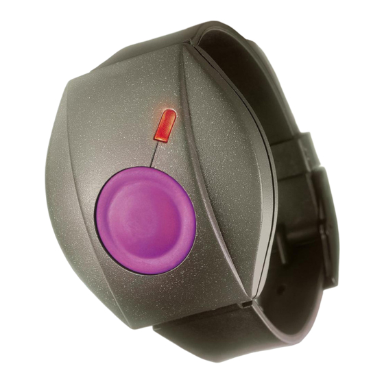
The MCT-211 is a miniature waterproof wrist-worn transmitter,
designed for use in advanced, high security alarm and remote
control systems. Transmission is initiated by depressing the
pushbutton at the center of the unit. When activated, the
transmitter sends out a 24-bit ID code and an alarm code, both
identifiable by compatible PowerCode type receivers. The ID
code assigned to each transmitter is factory-selected from over
16 million possible combinations, and is therefore unique and
virtually impossible to reproduce.
All MCT-211 units are supplied with a wrist band, to be worn like
a regular watch. Operating power is obtained from a coin-type,
3-volt lithium battery that can last up to 10 years.
An LED lights during transmission, indicating that the battery
63(&,),&$7,216
Frequency (MHz): 315, 404, 418, 433.92 or other frequencies
according to local requirements.
Modulation: ASK (ON-OFF keying)
Transmitter ID: 24-bit digital word, over 16 million possible code
combinations, pulse width modulation.
Total Message Length: 36 bits
Minimum Transmit Duration: 2 sec
Power Supply: 3-volt Lithium cell (Sanyo type CR-2025 or
equivalent).
Nominal Battery Capacity: 150 mAh
Current Consumption: 4.5 mA (during transmission), 1 µA in
the standby mode.
Battery Life: 3 to 5 years with about 3 transmissions per day; up
to 10 years with one transmission per day or none at all.
Battery Supervision:
Good battery - LED lights steadily upon activation.
Low battery - LED does not light upon activation.
Note: If transmission is still possible despite the battery condition,
the MCT-211 will send a low battery report to the receiver.
7(67,1*$1'0$,17(1$1&(
7HVWLQJD1HZ8QLW
Since the MCT-211 is supplied with the battery already installed,
the unit is practically ready to be tested.
A. "Teach" the target receiver the ID code of the tested
transmitter, as instructed in the target receiver's installation
manual.
B. Stand 3 m (10 ft) away from a target receiver and operate the
MCT-211 by depressing its transmit pushbutton. Verify that
the transmitter LED lights, indicating good battery condition.
Note: The LED will light for 2 seconds even if you press the
button for a shorter duration.
C. Observe that the receiver's LED lights, and make sure that the
receiver reacts as programmed.
D. Operate the transmitter from various locations within the area
covered by the target receiver to determine "dead" locations,
where transmission is blocked by walls and large objects, or
affected by structural materials.
Note: If dead/marginal zones are a problem, relocating the
receiver may improve the performance.
%DWWHU\5HSODFHPHQW
The original battery supplied with the transmitter can last up to 10
years if used sparingly (only a single transmission per day).
DE2451
Installation Instructions
voltage exceeds 2.4 V. If the
LED does not light during
transmission, the battery must
be replaced immediately. In
addition, a transmitter in which
the
battery
is
low
will
automatically
add
a
"low
battery" code to its outgoing
digital message. Compatible
receivers
are
designed
to
identify this code and operate
audible, visual or other alert
devices
Operating Temperature: 0° to 50°C (32° to 122°F).
Dimensions: Ø 35 mm (1.4 in.).
Weight: 25 g (0.9 oz).
Color: Black
Standards: Meets FCC part 15, ETS 300-220, ETS 300-683 and
MPT 1340.
This device complies with Part 15 of the FCC Rules and
RSS-210 of Industry and Science Canada. Operation is subject
to the following two conditions: (1) This device may not cause
harmful interference, and (2) this device must accept any
interference received, including interference that may cause
undesired operation.
CE Compliance
The 418 MHz and 433.92 MHz models of this device comply
with the European Council Directive EMC 89/336/EEC &
92/31/EEC, and bear the CE mark and certification.
Battery replacement will therefore be needed very rarely. To
replace the battery proceed as in 3.3, 3.4, 3.5, below.
2SHQLQJWKH&DVH
A. Put the transmitter face
down.
B. Loosen and remove the 4
screws shown in Figure 2.
Take care not to lose the
screws.
C. Turn the transmitter over.
Hold the base between the
fingers of one hand, and
pull the cover off.
D. Make sure that the rubber ring that serves as a seal is in
place around the rim of the base. If it comes loose, save it for
later use together with the screws.
Note: The strap pivots are seated in open grooves at the two
edges of the base. If you put the base on the table "on its
back", the pivots and the two sections of the strap will remain
in place.
Upon removing the cover, the top side of the transmitter module is
viewed (Fig. 3). The battery clip and battery will be out of sight -
they are both located on the bottom (hidden) side of the module.
Figure 1. MCT-211, General
View
Figure 2. Opening the Case
1
Advertisement

Related Manuals for Visonic MCT-211


Summary of Contents for Visonic MCT-211
-
Page 1: Installation Instructions
16 million possible combinations, and is therefore unique and battery" code to its outgoing virtually impossible to reproduce. digital message. Compatible All MCT-211 units are supplied with a wrist band, to be worn like receivers designed Figure 1. MCT-211, General a regular watch. - Page 2 VISONIC INC. (U.S.A.): 10 NORTHWOOD DRIVE, BLOOMFIELD CT. 06002-1911. PHONE: (860) 243-0833, (800) 223-0020 FAX: (860) 242-8094 VISONIC LTD. (UK): UNIT 1, STRATTON PARK, DUNTON LANE, BIGGLESWADE, BEDS. SG18 8QS. PHONE: (01767) 600857 FAX: (01767) 601098 ©VISONIC LTD. 1998 MCT-211 D-2451-0 NEW: DE2451- (REV. 1, 4/98)